A chopper is used to obtain controlled dc output from an unregulated or fixed dc input with minimal power loss. It is a solid-state switching device that uses thyristors, BJT, MOSFET. In this article let us see how controllable dc output voltage is obtained from a chopper. The average load voltage VL in a chopper is given by,
Where,
- T = Ton + Toff = Total time period of chopper
- Toff = Off-time period of the chopper
- Ton = On-time period of the chopper
- α = Ton/T = Duty cycle.
From the above equation, we can see that the output voltage is in proportion with the duty cycle. Thus by varying the duty cycle we can vary the load voltage. Depending upon this there are two techniques to control the output voltage of a chopper, they are,
- Time Ratio Control, and
- Current Limit Control.
Time Ratio Control :
Since frequency is the inverse of the time period T, α = Ton/T = Ton f. Hence, in time-ratio control, load voltage can be varied by varying the duty cycle ‘α’. As the duty cycle is directly proportional to frequency, we have two methods of voltage control in time-ratio control. One method of control is by keeping the frequency constant, known as constant frequency system and another method of control is by varying frequency, known as variable frequency system.
Constant Frequency System :
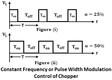
In this method, load voltage VL is controlled by maintaining frequency constant. As the frequency is kept constant, the time period also remains constant; whereas, the ON time (Ton) of the chopper is varied. As Ton is varied, the width of the pulses is varied, and hence constant frequency system is also known as “Pulse-width Modulation (PWM) Control”. The waveforms for VL with constant frequency for different duty cycles are shown below.
As shown in the above waveforms, the total time period (T) of the chopper is maintained constant; whereas, Ton is varied. In figure (i), Ton is 25% of T and in figure (ii), Ton is 50% of T. In this way, a chopper output voltage is produced and VL can be controlled.
Variable Frequency System :
In this method, VL can be controlled by controlling frequency. Since frequency is varied, the time period, T also varies. Hence, variable frequency is obtained either by varying Ton or Toff and keeping the other constant. Hence, as the time period varies, the frequency also varies and output voltage VL also varies.
Since frequency is varied, the variable frequency system is also known as “Frequency Modulation Control”. The below figure shows the frequency modulation control, with constant Ton and Toff is varied from 75% of T to 50% of T.
The below figure shows the frequency modulation control, with constant Toff and Ton is varied from 25% of T to 50% of T.
In comparison between the constant frequency and variable frequency system, variable frequency or frequency modulation control has the following disadvantages,
- A wide variation in the frequency is required in order to control the output voltage of the chopper, thus filter design becomes relatively difficult for such frequency variations.
- In frequency modulation control, the chopper may remain in OFF state for a large time period. This makes the load current discontinuous which is undesirable.
- A wide range of frequency variations to control the duty cycle can cause interference on telephone lines and signaling.
Therefore, most of the choppers employes pulse width modulation control over frequency modulation.
Current Limit Control (CLC) :
In this control technique, the output voltage is controlled by maintaining the load current between maximum Imax and minimum Imin value by switching ON and OFF the chopper. This method is also known as two-level control. In this method, the current is always continuous.
When dc supply voltage is given, the current starts to build up in the circuit and if it reaches the maximum value, the chopper is turned off. Once it is switched OFF, the load current flows through the freewheeling diode and starts decreasing. The chopper is again switched ON when the load current falls below the minimum value. Thus load current is maintained between maximum and minimum values as shown below.
The load current is continuous in this method and this control strategy can be performed either with the constant frequency or with constant turn ON (Ton) time. This control strategy is preferred only if the load contains energy storage elements.
The difference between Imax and Imin gives switching frequency of chopper and ripple content in load current is ΔI = Imax – Imin. The ripple content can be reduced by increasing the switching frequency which in turn results in high switching losses.


Good information. please add 3phase half and full controlled converters